11.3.1Introduction#
Aerospace engineering designs and operates systems that work within and beyond the Earth’s atmosphere, and its missions are spatial problems at their core. Rendezvous and docking (RVD), on-orbit servicing (OOS), debris inspection, and planetary landing and roving all depend on estimating three-dimensional structure and relative motion, often of a non-cooperative target that carries no markers, while communication delays rule out continuous ground control. Both spacecraft autonomy (e.g., , guidance, navigation, and control) and human-in-the-loop operations (e.g., , situational awareness for ground controllers) therefore rest on spatial perception and reasoning over geometry, relative motion, semantics, and physical constraints.
Aerospace engineering is thus a demanding deployment target for the perception and reasoning capabilities surveyed in Part III: the detection, segmentation, pose-estimation, and 3D-reconstruction techniques of Chapter 6 and the planning and decision-making methods of Chapter 7 are here specialized to non-cooperative orbital targets, extreme illumination, and long-horizon autonomy under radiation-hardened compute and communication latency.
11.3.2System Overview#
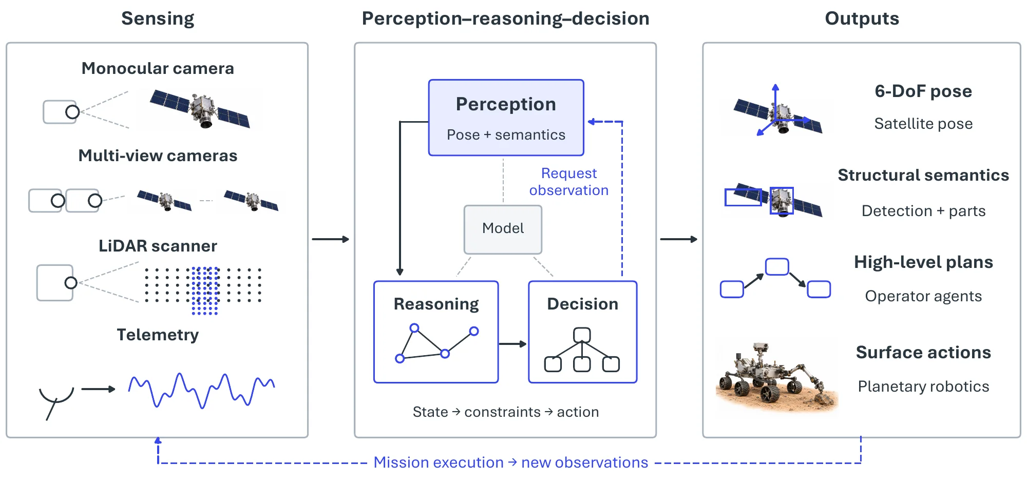
The value of spatial intelligence in aerospace lies less in any single perception module than in the closed autonomy loop it serves (Figure 11.12): onboard and ground-based sensing (monocular and multi-view cameras, LiDAR, telemetry) feeds a perception-reasoning-decision core, whose commands change the scene that is sensed next. The four pivotal tasks treated below are complementary stages of this loop. Satellite pose estimation supplies the geometric anchor, recovering where a target is and how it is oriented; spacecraft detection, segmentation, and parts recognition enrich that anchor with structural semantics, identifying what the target is and which functional components it exposes; operator agents lift this perceptual state into high-level reasoning, planning, and human-facing decision support; and planetary robotics closes the loop on the surface, coupling perception, localization, and planning into physical exploration and sampling. Table 11.5, after Task-4, consolidates representative benchmarks and metrics across all four.
11.3.3Pivotal Task-1: Satellite Pose Estimation#
Vision-based satellite pose estimation predicts the 6-DoF relative position and orientation of a target spacecraft from monocular or multi-view imagery; it is the geometric anchor of the autonomy loop and a prerequisite for rendezvous, docking, and on-orbit servicing. It specializes the 6-DoF estimation problem of Chapter 6 to a hostile setting: harsh illumination, specular reflections, little texture, and a severe gap between the synthetic images models are trained on and the real images they meet in orbit. Figure 11.13 traces the pipeline from method to evaluation.
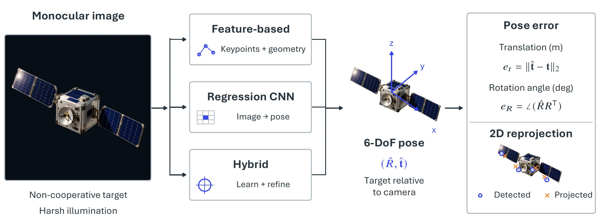
Traditional methods relied on hand-engineered features (e.g., , Harris corners, SIFT, SURF, and ORB) or model-based tracking [2792], which are sensitive to noise and domain shift, and deep learning has since become dominant [2793]. The first deep models regress the pose directly with CNNs [2794], as in the Spacecraft Pose Network (SPN) [2795], a GoogLeNet-based network [2796], and a VGG backbone [2797], trained on synthetic data and on laboratory imagery that simulates an on-orbit assembly operation. SPNv2 [2798] made multi-task learning the prevailing design: its shared encoder jointly predicts keypoints, a direct pose regression, and foreground segmentation, and it narrows the synthetic-to-real gap by online domain refinement, adapting the network’s normalization layers on unlabeled target imagery at deployment. Hybrid pipelines estimate a coarse pose with a deep model and refine it with geometry-based optimization, keeping the final estimate physically consistent; early work classified discretized viewpoints with a CNN [2799], and the same coarse-to-fine pattern now extends to 6-DoF tracking with stereo event cameras [2800].
SPEED [770] and SPEED+ [2801] are the standard testbeds (Table 11.3): both pair a large synthetic training set with laboratory hardware-in-the-loop test images, so that the synthetic-to-real gap is measured rather than assumed, and the Satellite Pose Estimation Challenge built on them fixed common training regimes, input formats, and metrics [2802]. CubeSat-CDT [2803] adds trajectories of a symmetric target, so that temporal methods and pose ambiguity can be evaluated. Evaluation reports translation and rotation error as defined for SPEED [770], often with 2D reprojection or keypoint error [2794]; results are given separately on synthetic and real test sets, and robustness to illumination, occlusion, and background clutter is probed explicitly [2798].
| Dataset | Image | Classes | Resolution | Rendering | Trajectories | Public | |
| Synthetic | Non-synthetic | ||||||
| SPARK [2804] | 150k | - | 11 | sim | ✓ | ||
| SPEED [770] | 15k | 305 | 1 | sim + lab | ✓ | ||
| SPEED+ [2801] | 60k | 10k | 1 | sim + lab | ✓ | ||
| URSO [2793] | 15k | - | 2 | sim | ✓ | ||
| SwissCube [747] | 50k | - | 1 | sim | ✓ | ✓ | |
| Cygnus [2805] | 20k | 540 | 1 | sim + real | |||
| Prisma12K [2806] | 12k | - | 1 | sim | |||
| Prisma25 [2806] | - | 25 | 1 | -NA- | real | ||
| CubeSat-CDT [2803] | 14k | 8k | 1 | sim + lab | ✓ | ✓ | |
11.3.4Pivotal Task-2: Spacecraft Detection, Segmentation, and Parts Recognition#
Detection, segmentation, and parts recognition enrich the geometric anchor of Task-1 with structural semantics, telling what the target is and which functional components it exposes; proximity operations, on-orbit servicing, debris inspection, and collision avoidance all depend on this. The detection and segmentation machinery of Chapter 6 meets the obstacles of Task-1 here (strong illumination variation, specular metallic surfaces, little texture) and, in addition, a scarcity of annotated real imagery. The stack runs from coarse presence to fine structure: detection localizes the spacecraft, segmentation delineates its silhouette, and parts recognition resolves its components, as Figure 11.14 illustrates.
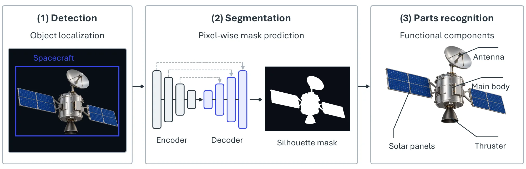
Convolutional and transformer architectures now carry all three stages [2807]. Detection is formulated as bounding-box or keypoint localization, with lightweight saliency-driven detectors for onboard compute, while encoder–decoder networks, pyramid attention modules, and hybrid 2D/3D architectures delineate silhouettes and component boundaries [2808]. Parts recognition (solar panels, antennas, thrusters, reflectors) often adds semantic priors or 3D geometric reasoning to stay robust under occlusion. Two recent lines reduce the dependence on manual labels: prompt-guided Segment Anything (SAM) automates the annotation of space targets [2809], and diffusion priors support few-shot segmentation and adaptation to unseen spacecraft [2810].
The datasets in Table 11.4 differ along a few axes. Labels range from whole-object masks (SwissCube [747], a pose dataset that also provides CubeSat masks, and SPARK [2804]) and object-level boxes (STAR-24K [2811]) to component labels, from a single component (the solar panels of the Tsinghua dataset [2812]) up to nine (Spacecraft-DS [2813]). Most are rendered (Unity3D for SPARK, Unreal Engine 4 for UESD [2814]), whereas Spacecraft-DS uses hardware-in-the-loop capture to narrow the synthetic-to-real gap. The Adelaide dataset [2815] fixed the common three-component scheme (solar panel, main body, antenna), which Shao et al. [2807] extended to video sequences rendered under three illumination conditions and several relative-motion modes; Zhao et al. [2808] carried the same labels to 3D point clouds, and NCSTP [2816] raised the scale to 200,000 images of satellites, debris, and rocks. Detection is scored by mean average precision and segmentation by IoU, as in Chapter 6.
| Dataset | #Images | #Satellite Models | Segmentation Level | #Components |
| SwissCube [747] | 50,000 | 1 | Global | 0 |
| UESD [2814] | 10,000 | 33 | Component | 5 |
| SPARK [2804] | 150,000 | 10 | Global | 0 |
| STAR-24K [2811] | 24,451 | - | Global | - |
| NCSTP [2816] | 200,000 | 16 | Component | 4 |
| Tsinghua Satellite Dataset [2812] | 18,381 | - | Component | 1 |
| Adelaide Satellite Dataset [2815] | 3,117 | - | Component | 3 |
| Satellite Component Video Dataset [2807] | 32,402 | 13 | Component | 3 |
| Spacecraft-DS [2813] | 1,602 | 2 | Component | 9 |
| 3D component point clouds (Zhao et al.) [2808] | - | 33 | Component | 3 |
11.3.5Pivotal Task-3: Operator Agents#
Operator agents lift the perceptual state recovered by Tasks 1 and 2 into reasoning, planning, and decision support, monitoring, interpreting, and controlling spacecraft systems to reduce operator workload and allow more autonomous mission execution. They are the aerospace instance of the planning and decision-making capabilities of Chapter 7. Rooted in rule-based and model-driven architectures, their role has expanded from health monitoring and scheduling to high-level control in dialogue with human experts, a history that runs from symbolic planning through multi-agent coordination to foundation-model reasoning (Figure 11.15).
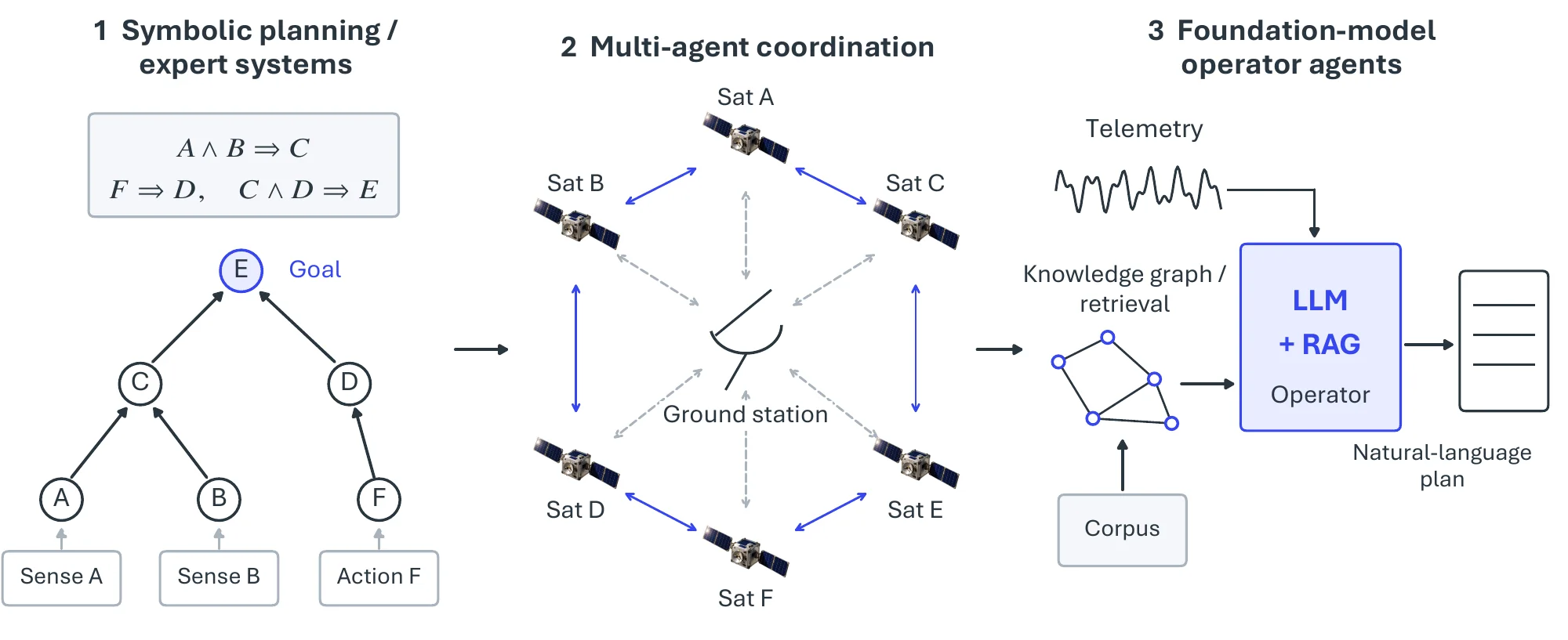
Early operator-agent architectures were built on symbolic reasoning, constraint-based planning, and expert-system principles. The Remote Agent Experiment [2817] and early autonomous spacecraft-agent prototypes [2818] demonstrated onboard planning, diagnosis, and execution in deep-space missions. As autonomy requirements grew, multi-agent planning frameworks [2819, 225] were introduced to coordinate heterogeneous spacecraft, manage distributed sensing, and schedule jointly across satellite constellations. Large language models changed the design: recent work [2820, 2821] uses LLMs as operator agents that interpret telemetry, generate action plans, respond to anomalies, and follow natural-language mission specifications, and fine-tuned LLMs [2822, 2823, 2824, 2825] have been tested in simulators such as Kerbal Space Program (KSP) for guidance, navigation, and control. To meet the interpretability and safety requirements of mission-critical decisions, other studies integrate retrieval-augmented generation (RAG) [2826], domain knowledge graphs [2827], and structured symbolic reasoning, while hybrid architectures such as MCP-based multi-component agents [2828] combine small specialized models with foundation models to balance computational cost and reasoning depth, particularly for on-orbit servicing.
Evaluation environments followed the same path. The Remote Agent Experiment [2817] supplied real mission scenarios for onboard planning and diagnosis, and multi-agent planning studies [2819] supply constellation-level scheduling, resource-allocation, and communication constraints. LLM agents are tested in simulation, chiefly in KSP [2825] and in the KSPDG suite of SpaceGym [2829], a set of multi-agent pursuit–evasion differential games built in the KSP engine. Classical agents are scored on planning optimality, constraint satisfaction, fault-diagnosis accuracy, and task completion; LLM agents are additionally judged on adherence to safety constraints, robustness to shifts in telemetry or mission context, and the interpretability of their decisions, which is why uncertainty estimation and human-in-the-loop verification recur throughout this work.
11.3.6Pivotal Task-4: Planetary Robotics#
Planetary robotics closes the autonomy loop on the surface, coupling the perception, localization, and planning capabilities of Chapters 6 and 7 into exploration, navigation, and sampling on the Moon, Mars, and small bodies. Unlike orbital operations, surface missions face uneven and unstructured terrain, delayed and limited communication, restricted sensing, and long stretches of autonomy without continuous human supervision. Figure 11.16 layers the autonomy stack from perception and mapping through hierarchical decision-making to vision-guided manipulation.

Surface robots are organized around a mobility stack that couples perception, localization, mapping, planning, and control, with manipulation and science operations integrated at the task level. Feature tracking, visual odometry, and stereo reconstruction estimate rover motion and build local 3D models of rugged terrain, a capability flown since the Mars Exploration Rovers [2830]. The Enhanced AutoNav (ENav) system on NASA’s Perseverance rover [2831] builds onboard 3D terrain maps, evaluates hazards, and plans safe local traverses under severe computational and communication constraints, and it evaluated terrain over a large majority of the rover’s traversed distance. This autonomy remains embedded in a human-supervised workflow: ground operators specify science goals and route segments, and onboard autonomy resolves local navigation and hazard avoidance.
Research and analogue-testbed systems extend these capabilities to multiple robots, where cooperative visual navigation and shared mapping improve coverage and robustness [2832]. Hierarchical frameworks [2833] decompose behavior across temporal and functional layers, balancing reactive locomotion and obstacle avoidance with deliberative path planning, task scheduling, and mission-level reasoning under safety, power, communication, and resource constraints.
Vision-guided manipulation supports sample collection and instrument deployment by coupling image-based pose estimation with position-controlled or compliant manipulation suited to contact with natural terrain [2834]. Learning-based methods are increasingly explored for terrain classification, slip prediction, and traversability estimation, but model-based perception, localization, and planning remain central: safety requirements are stringent, mission-representative labeled data is scarce, onboard computation is constrained, and purely data-driven methods are hard to validate for mission-critical use. Evaluation therefore combines physics-based simulators, mission-derived datasets, and laboratory or analogue-field testbeds that model illumination, dust, wheel–soil interaction, and communication delay, and it reports localization accuracy, map quality, hazard-aware traversal, task completion, and energy use.
| Pivotal task | Benchmark | Representative method / system | Headline metric |
| Pose estimation | SPEED / SPEED+ [770, 2801] | Multi-task / domain-adaptive CNN [2798] | Translation + rotation error |
| Pose estimation | CubeSat-CDT [2803] | Cross-domain regression [2794] | 2D reprojection error |
| Detection & parts | Adelaide / SPARK [2815, 2804] | Encoder-decoder segmentation [2808] | mAP |
| Detection & parts | NCSTP [2816] | SAM-based prompt segmentation [2809] | mAP / IoU |
| Operator agents | KSPDG / SpaceGym [2829] | Fine-tuned LLM agent [2825] | Maneuver success rate |
| Operator agents | Deep Space 1 flight experiment [2817] | Symbolic planner / diagnosis [2818] | Task completion |
| Planetary robotics | Mars rover traverses [2831] | Visual odometry [2830] | Localization drift |
| Planetary robotics | Hierarchical-autonomy suites [2833] | Layered decision-making [2833] | Task-completion / safety |
11.3.7Established Tools and Systems#
Simulators and rendering engines. Because real orbital imagery is scarce and flight opportunities are expensive, most perception research is trained and validated in simulation. General-purpose game and physics engines have been repurposed as space testbeds: Unity3D and Blender drive the synthetic rendering pipelines behind the SPARK [2804] and satellite-component [2807] datasets, while the Kerbal Space Program1 engine underpins LLM-agent guidance-navigation-control studies [2825]. For decision-making, SpaceGym2 [2829] packages its OrbitDefender2D gridworld games and the KSPDG suite as standardized non-cooperative game environments, and robotics simulators such as NVIDIA Isaac Sim3 and Gazebo4 provide the wheel-soil and sensor models used to prototype planetary-rover autonomy.
Public challenges. The Satellite Pose Estimation Challenge [2802], run by Stanford’s Space Rendezvous Laboratory and the European Space Agency on its Kelvins platform5, set the protocols that pose estimation now follows, and its SPEED+ edition [2801] made the synthetic-to-real gap the explicit test.
Flight-proven autonomy systems. The NASA Remote Agent [2817], flown on Deep Space 1, remains the canonical reference for onboard planning, diagnosis, and execution. On planetary surfaces, rover visual odometry [2830] and the Enhanced AutoNav stack flown on Perseverance [2831] set the operational baseline against which hierarchical-autonomy and learning-augmented methods are measured, and current work pairs such flight-qualified stacks with foundation-model agents [2828].
11.3.8Challenges#
Orbital and planetary environments differ from terrestrial ones in ways that terrestrial data does not cover, and the open problems follow the pipeline: the data gap that limits perception, the compute budget that limits deployment, and the trustworthiness requirements that limit certification.
The Unresolved Sim-to-Real Domain Gap. Autonomous space systems, such as those performing on-orbit servicing or debris removal, are trained largely on simulated data, and simulators do not reproduce the high-dynamic-range lighting of orbit (e.g., , solar glare and deep shadow), intricate material reflections, or sensor degradation such as radiation noise. Models consequently lose accuracy on real imagery, as the hardware-in-the-loop test sets of the pose-estimation challenges show [2802, 2801], which keeps domain adaptation and domain randomization central to the field.
Computational Constraints and Real-time Operation. Spacecraft hardware is bound by size, weight, and power (SWaP) limits and must use radiation-hardened processors that are far less powerful than ground-based GPUs. Running 6-DoF pose estimation or SLAM at the update rates that proximity operations require on such computers calls for model compression, lightweight architectures, and hardware-aware optimization that preserve accuracy while cutting latency and power consumption.
Assuring Trustworthiness and Robustness in Extreme Conditions. Space missions are safety-critical, so perception must hold up under extreme visual ambiguity, such as estimating the pose of highly symmetric targets like CubeSats [2803] or navigating where standard reference signals are unavailable. Deployed systems also explain little about their own failures, so operators cannot easily trace a perception anomaly (e.g., , a pose error caused by sensor saturation) to its root cause in time to intervene. Formal verification and interpretable models that guarantee predictable behavior across operating extremes remain open problems.